|
Source: © 2001, San Bergmans, Oisterwijk, The Netherlands http://www.sbprojects.com/
The cheapest way to remotely control a device within a visible range is via Infra-Red light. Almost all audio and video equipment can be controlled this way nowadays. Due to this wide spread use the required components are quite cheap, thus making it ideal for us hobbyists to use IR control for our own projects.
Infra-Red actually is normal light with a particular colour. We humans can't see this colour because its wave length of 950nm is below the visible spectrum. That's one of the reasons why IR is chosen for remote control purposes, we want to use it but we're not interested in seeing it. Another reason is because IR LEDs are quite easy to make, and therefore can be very cheap.
Unfortunately for us there are many more sources of Infra-Red light. The sun is the brightest source of all, but there are many others, like: light bulbs, candles, central heating system, and even our body radiates Infra-Red light. In fact everything that radiates heat, also radiates Infra-Red light.
Modulation is the answer to make our signal stand out above the noise. With modulation we make the IR light source blink in a particular frequency. The IR receiver will be tuned to that frequency, so it can ignore everything else. In serial communication we usually speak of 'marks' and 'spaces'. The 'space' is the default signal, which is the off state in the transmitter case. No light is emitted during the 'space' state. During the 'mark' state of the signal the IR light is pulsed on and off at a particular frequency. Frequencies between 30kHz and 60kHz are commonly used in consumer electronics. Please note that the 'marks' and 'spaces' are not the 1-s and 0-s we want to transmit. The real relationship between the 'marks' and 'spaces' and the 1-s and 0-s depends on the protocol that's being used. More information about that can be found on the pages that describe the protocols.
The transmitter usually is a battery powered handset. It should consume as little power as possible, and the IR signal should also be as strong as possible to achieve an acceptable control distance. Preferably it should be shock proof as well. Many chips are designed to be used as IR transmitters. The older chips were dedicated to only one of the many protocols that were invented. Nowadays very low power microcontrollers are used in IR transmitters for the simple reason that they are more flexible in their use. When no button is pressed they are in a very low power sleep mode, in which hardly any current is consumed. The processor wakes up to transmit the appropriate IR command only when a key is pressed. Quartz crystals are seldom used in such handsets. They are very fragile and tend to break easily when the handset is dropped. Ceramic resonators are much more suitable here, because they can withstand larger physical shocks. The fact that they are a little less accurate is not important. The current through the LED (or LEDs) can vary from 100mA to well over 1A! In order to get an acceptable control distance the LED currents have to be as high as possible. A trade-off should be made between LED parameters, battery lifetime and maximum control distance. LED currents can be that high because the pulses driving the LEDs are very short. Average power dissipation of the LED should not exceed the maximum value though. You should also see to it that the maximum peek current for the LED is not exceeded. All these parameters can be found in the LED's data sheet.
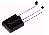
Many different receiver circuits exist on the market. The most important selection criteria are the modulation frequency used and the availability in you region.
In the picture above you can see a typical block diagram of such an IR receiver. Don't be alarmed if you don't understand this part of the description, for everything is built into one single electronic component.
Please note that the amplifier is set to a very high gain. Therefore the system tends to start oscillating very easily. Placing a large capacitor of at least 22µF close to the receiver's power connections is mandatory to decouple the power lines. Some data sheets recommend a resistor of 330 Ohms in series with the power supply to further decouple the power supply from the rest of the circuit. There are several manufacturers of IR receivers on the market. Siemens, Vishay and Telefunken are the main suppliers here in Europe. Siemens has its SFH506-xx series, where xx denotes the modulation frequency of 30, 33, 36, 38, 40 or 56kHz. Telefunken had its TFMS5xx0 and TK18xx series, where xx again indicates the modulation frequency the device is tuned to. It appears that these parts have now become obsolete. They are replaced by the Vishay TSOP12xx, TSOP48xx and TSOP62xx product series. |
 Although we humans can't see the Infra-Red light emitted from a remote control doesn't mean we can't make it visible.
 A simple transistor circuit can be used to drive the LED. A transistor with a suitable HFE and switching speed should be selected for this purpose.
  The normal driver, described above, has one disadvantage. As the battery voltage drops, the current through the LED will decrease as well. This will result in a shorter control distance that can be covered.
 As I said before, all these blocks are integrated into a single electronic component. There are many different manufacturers of these components on the market. And most devices are available in several versions each of which are tuned to a particular modulation frequency.